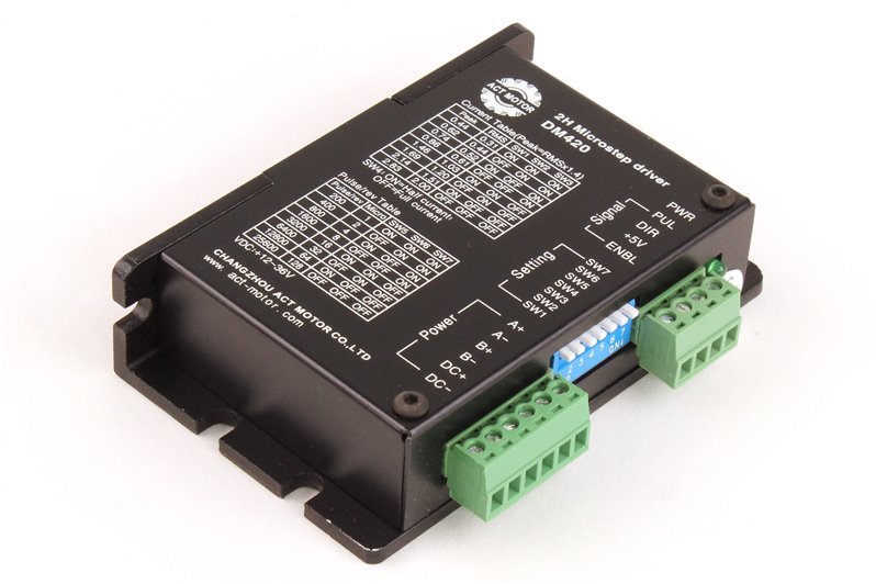
DM420, 2 Phase Digital Stepper Drive; Max 36 VDC / 2.0A (kopie)
€16,49
Op voorraad
– Supply voltage from 12VDC to 36VDC
– Opto-isolated signal I/O
– Overvoltage, under voltage, overcorrect, phase short circuit protection
– 8 channels subdivision and automatic idle-current reduction
– 8 channels output phase current setting
– Offline command input terminal
– Motor torque is related with speed, but not related with step/revolution
– High start speed
– High hording torque under high speed
Pins assignments and description:
1) Connector Pins Configurations
| Pin Function | Details |
| PUL +,PUL- | Pulse signal, PUL+ is the positive end of pulses input pin
PUL- is the negative end of pulse input pin |
| DIR+,DIR- | DIR signal: DIR+ is the positive end of direction input pin
DIR- is the negative end of direction input pin |
| ENBL+ | Enable signal: ENBL+ is the positive end of direction input pin. This signal is used for enabling/disabling the driver. High level for enabling the driver and low level for disabling the driver. |
| ENBL- | ENBL- is the negative end of direction input pin. Usually left unconnected (enabled) |
3.Function choice ( Using DIP pins to achieve this function)
1) Micro step resolution is set by SW 5,6,7,8 of the DIP switch as shown in the following table
| SW5 | ON | OFF | ON | OFF | ON | OFF | ON | OFF |
| SW6 | ON | ON | OFF | OFF | ON | ON | OFF | OFF |
| SW7 | ON | ON | ON | ON | OFF | OFF | OFF | OFF |
| Pulse/rev | 200 | 400 | 800 | 1600 | 3200 | 6400 | 12800 | 25600 |
| Micro | 1 | 2 | 4 | 8 | 16 | 32 | 64 | 128 |
2) Standstill current setting
SW4 is used for this purpose. OFF meaning that the standstill current is set to be half of the selected dynamic current and ON meaning that standstill is set to be the same as the selected dynamic current.
3) Output current setting:
The first three bits (SW 1, 2, 3)of the DIP switch are used to set the dynamic current. Select a setting
Closest to your motor’s required current
| SW1 | SW2 | SW3 | PEAK | RMS |
| ON | ON | ON | 0.44 A | 0.31 A |
| OFF | ON | ON | 0.62 A | 0.44 A |
| ON | OFF | ON | 0.74 A | 0.52 A |
| OFF | OFF | ON | 0.86 A | 0.61 A |
| ON | ON | OFF | 1.46 A | 1.03 A |
| OFF | ON | OFF | 1.69 A | 1.20 A |
| ON | OFF | OFF | 2.14 A | 1.51 A |
| OFF | OFF | OFF | 2.83 A | 2.00 A |
Troubles
| Alarm indicator | Reasons | Measures |
| LED off turn | Wrong connection for power | Check wiring of power |
| Low-voltages for power | Enlarge voltage of power | |
| Motor doesn’t run, without holding torque | Wrong connection of stepper motor | Correct its wiring |
| RESET signal is effective when offline | Make RESET ineffective | |
| Motor doesn’t run, but maintains holding torque | Without input pulse signal | Adjust PMW & signal level |
| Motor runs wrong direction |
Wrong wires’ connection |
Change connection for any of 2 wires |
| Wrong input direction signal | Change direction setting | |
| Motor’s holding torque is too small | Too small relative to current setting | Correct rated current setting |
| Acceleration is too fast | Reduce the acceleration | |
| Motor stalls | Rule out mechanical failure | |
| Driver does not match with the motor | Change a suitable driver |


